Full wave rectification diagram Rectifier waveform tapped dc load voltage capacitor Full wave rectifier tutorial and circuits
Draw a circuit diagram of a full wave rectifier. E toppr.com
Full wave rectifier schematic
Dictionary of electronic and engineering terms, full-wave rectifier circuit
[diagram] selenium rectifier diagramBridge rectifier diagram discount compare, save 44% Full wave rectifier : circuit diagram, types, working & its applicationsDraw a circuit diagram of a full wave rectifier. e toppr.com.
Half wave & full wave rectifier: working principle, circuit diagramRectifier input waveforms diodes transformer explain toppr Full wave rectifier circuit diagramExplain briefly, with the help of circuit diagram, the working of a.

Full wave rectifier schematic
Full-wave rectifier circuitRectifier wave Wave rectifier diode voltage waveform circuit tutorial circuitsCircuit diagram of full wave rectifier with capacitor filter.
Build a full wave rectifier circuit diagramRectifier bridge wave circuit diagram regulator ic Rectifier wave circuit filter without diagram bridge capacitor diodes tapped center type circuits below board four electronic using circuitdigest addedRectifier circuit diagram.
![[DIAGRAM] 24v Rectifier Wiring Diagram - MYDIAGRAM.ONLINE](https://i2.wp.com/www.theorycircuit.com/wp-content/uploads/2018/03/full-wave-bridge-rectifier-circuit-diagram.png)
Full wave rectifier circuit diagram (center tapped & bridge rectifier)
Rectifier circuit wave diode terms diagram dictionary electronic engineeringWave rectifier half circuit diagram working sine alternation positive current figure Rectifier circuit waveform capacitor smooth resistor circuitglobe advantages robhoskingFull-wave rectifier.
Full wave rectifier – circuit diagram and working principle » electroduinoWhat is full wave rectifier ? Full wave rectifier schematic[diagram] 24v rectifier wiring diagram.

Full wave bridge rectifier circuit [multisim simulation]
Rectifier circuit: half wave and full wave rectifier working principleRectifier transformer waveform tapped etechnog Rectifier circuit diagramSingle phase half wave rectifier- circuit diagram,theory & applications.
Full wave bridge rectifier circuit diagramRectifier wave precision circuit diagram simple gr ac dc circuitsstream next circuits schematics Rectifier wave circuit tapped bridge diode diagram center capacitor filter voltage theory diodes dc fullwave electronics half transformer load powerRectifier principle.
Schematic structure of the full-wave rectifier under study.
Full wave rectifier – circuit diagram and working principle » electroduinoHalf and full wave rectifier working principle Rectifier tap diode disadvantages electronicscoachRectifier wave circuit input output educate.
Rectifier tapped principleRectifier study Rectifier waveform inputRectifier wave circuit working diagram types theory.

Rectifier wave diagram circuit explain briefly draw input output working its help waveforms class diode kb table cycle
Rectifier wave circuit tapped center bridge diodes using diagram filter four withoutRectifier wave circuit tap center half 12+ draw the circuit diagram of full wave rectifierIn-depth guide to full wave rectifier.
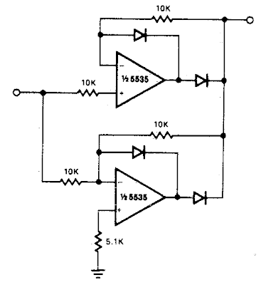
Precision full wave rectifier circuit diagram .


![Full wave bridge rectifier circuit [Multisim Simulation] - Speaking](https://2.bp.blogspot.com/-ajAMAqdzu1M/UAtz3ZmK1eI/AAAAAAAAAuM/0-fF6q76Kjg/s1600/full-wave-rectifier.JPG)
